__What Is Multi Jet Fusion Technology?__

PRODUCTION MJF 3D PRINTING Services

Multi Jet Fusion (MJF) is an advanced 3D printing technology that uses an inkjet array to selectively apply fusing and detailing agents across a bed of nylon powder. An energy source then passes over the bed, fusing each layer.

±25μm

Accuracy

3-5Days

Turnaround

5+

Materials

50k+

Parts Delivered
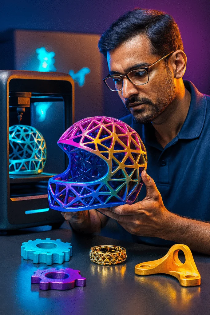
Why Multi Jet Fusion Technology ?

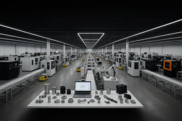
Industrial-Grade MJF 3D Printing at Production Scale

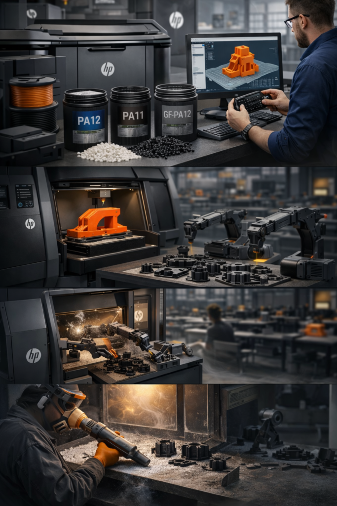
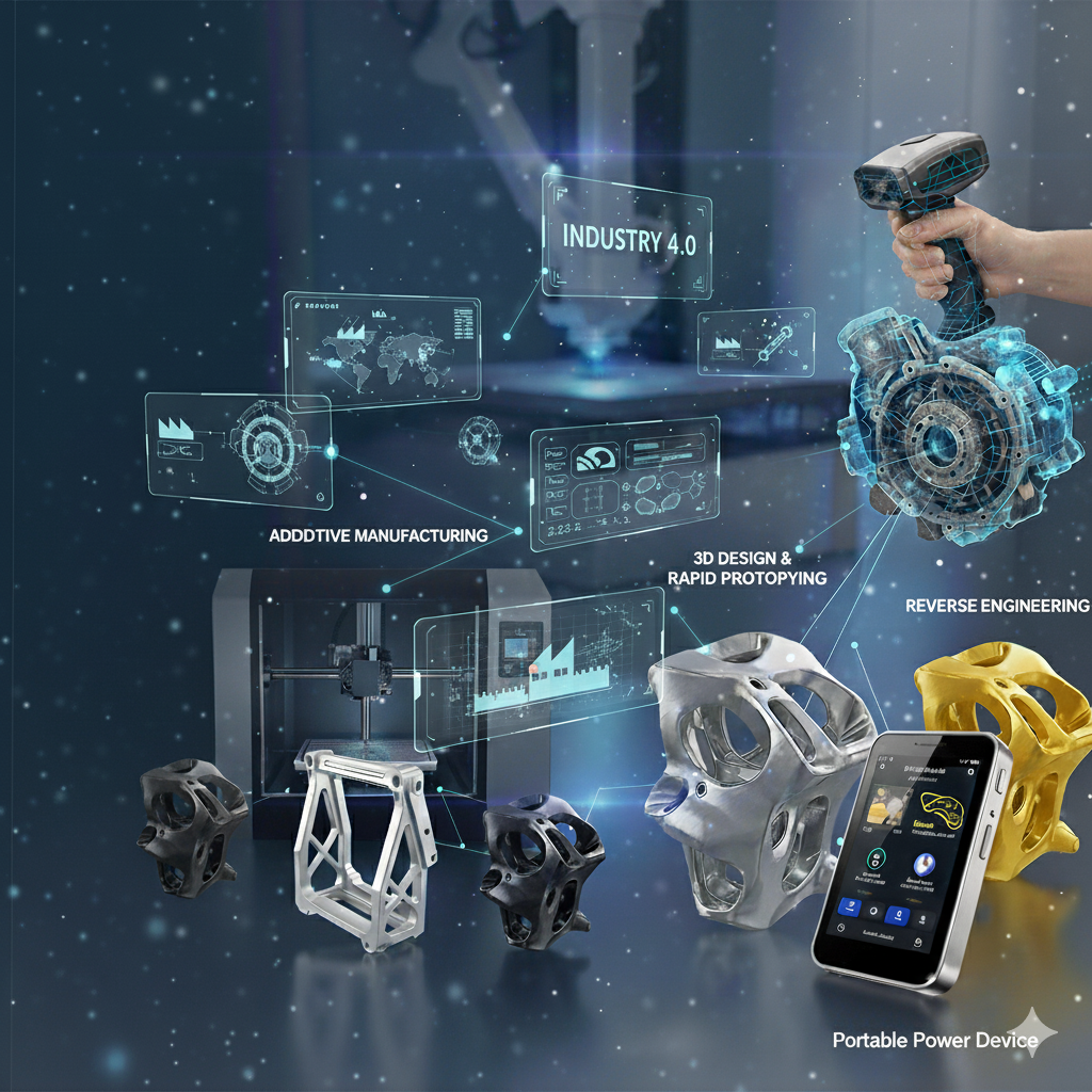
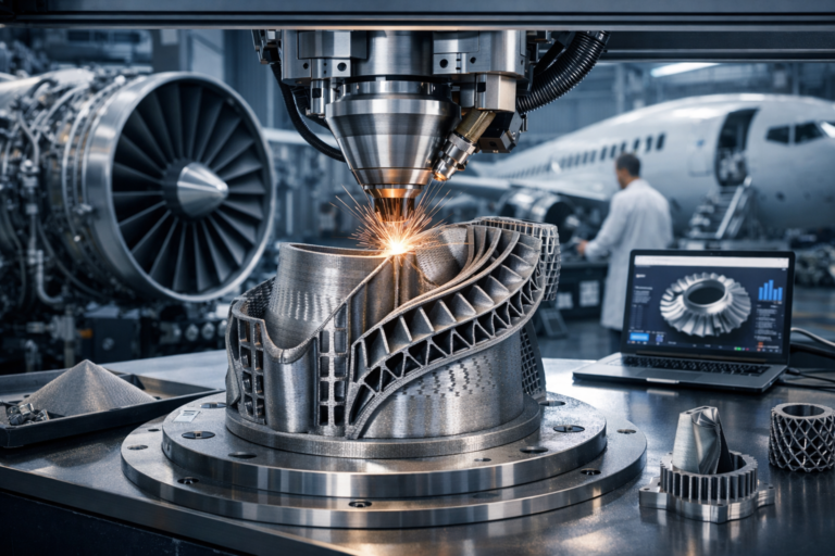
At Indium-Protofy3D Our Multi Jet Fusion technology delivers isotropic mechanical properties, sub-0.3mm tolerances, and true production volumes — engineered for the most demanding applications in aerospace, automotive, and advanced manufacturing. 

Key Features

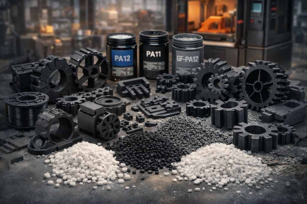
  • Biocompatible material options
  • High-temperature resistant polymers
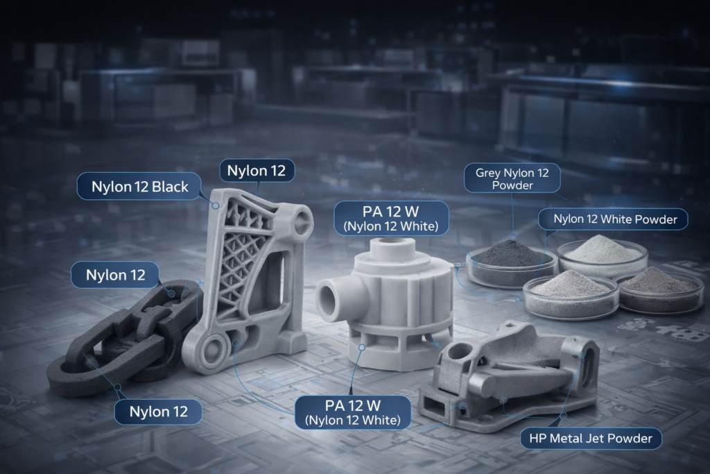
  • Flexible and rigid material choices
  • Food-safe certified materials
  • Custom material development available

Why MJF Outperforms Conventional 3D Printing

Production-Ready Speed

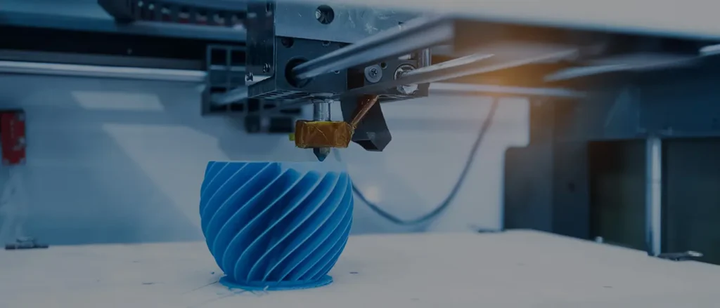
MJF processes an entire powder bed layer simultaneously, enabling throughput that’s 10× faster than single-point SLS systems. Parts-in-hand in 3–5 business days.

Up to 4,115 cm³/hr build rate

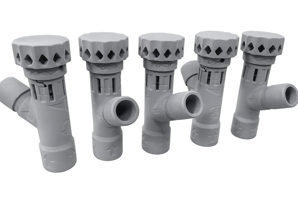
Superior Surface Quality

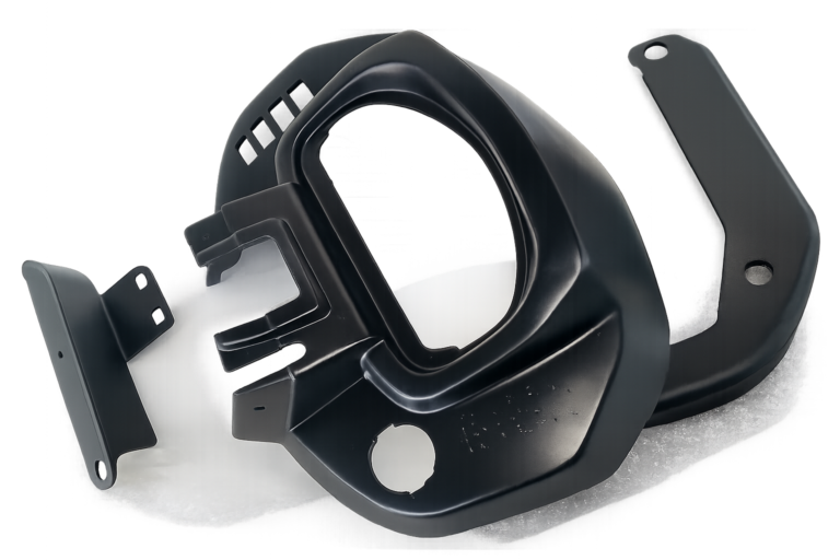
The detailing agent at part boundaries produces a sharper, smoother surface than SLS, reducing post-processing time and improving cosmetic quality for customer-facing components.

Ra 7–12μm as-built finish

Isotropic Mechanical Strength

Unlike FDM which creates weak Z-axis bonds between layers, MJF fuses each layer into a continuous, homogeneous structure — delivering equal strength in all three axes.

XYZ tensile strength within 5%

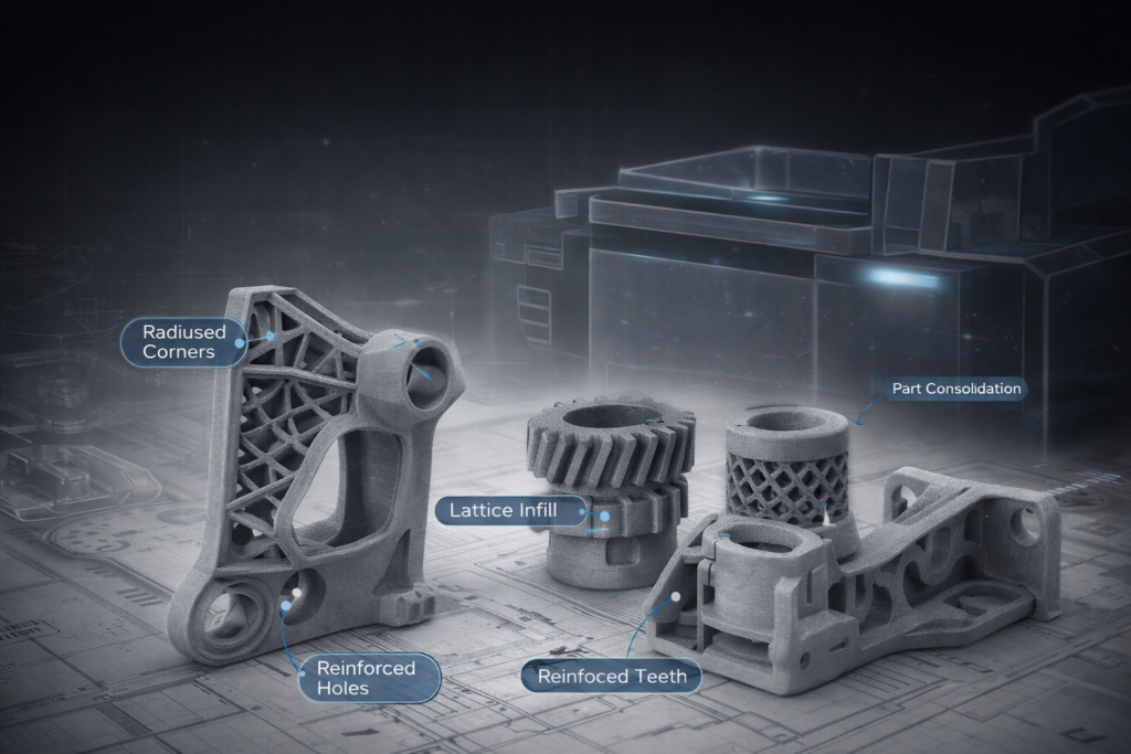
Support-Free Geometry

Parts are self-supported by unfused powder during the build, enabling complex internal channels, organic geometries, and interlocking assemblies impossible with support-dependent processes.

Zero support material waste

How MJF 3D Printing Process Works?

Fused deposition modeling streamlined workflow designed for efficiency and quality

Powder Bed Layering

A recoating unit spreads a uniform 80μm layer of thermoplastic powder (PA12 or other material) across the entire build platform.

Agent Jetting

Thermal inkjet arrays simultaneously deposit fusing agent on part geometry and detailing agent at boundaries — at 1200 DPI resolution.

Infrared Fusion

The build platform passes through an infrared energy zone. Fusing agent absorbs IR energy, melting and fusing powder particles into a dense, isotropic solid.

Cooling & Extraction

After the full build completes, the print cake undergoes a controlled cooling cycle to minimise thermal stresses and achieve dimensional accuracy.

Post-Processing

Parts are removed from the powder cake, media-blasted to remove loose powder, and optionally dyed, coated, or machined to specification.

__Why Partner with Us for HP Multi Jet Fusion Technology__

The Production-Scale Advantage Multi Jet Fusion Capability

Our HP Multi Jet Fusion  3D printing services At Indium-Protofy3D , delivers production-grade nylon parts at speeds no other additive process can match — isotropic strength, consistent surface finish, and full-colour capability at industrial scale.

__Why Choose Us__ Why MJF Outperforms Conventional 3D Printing?

Precision Capabilities & Multi Jet Fusion 5200 Manufacturing Specifications

Professional HP Multi Jet Fusion 5200 systems creates parts with excellent mechanical properties, fine detail, and smooth surface finish at production speeds that outpace traditional manufacturing methods.

BENEFITS

  • Durable, functional end-use parts
  • No support structures required
  • High packing density → cost-efficient batches
  • Consistent quality across builds

LIMITATIONS

  • Limited materials primarily Nylon-PA12, PA22, PA11)
  • Higher cost for single parts
  • Requires depowdering & finishing
  • Limited native color options (typically grey)
LARGE_BUILD_VOLUME
LAYER_RESOLUTION
DIMENSIONAL_ACCURACY
Print Speed
Support Structures
Minimum Wall Thickness
Surface Roughness
FILE_FORMATS
STANDARD_LEAD_TIME
RUSH_LEAD_TIME
POST_PROCESSING
CERTIFICATIONS
Technology

MJF vs SLS vs FDM vs SLA: A Technical Comparison

Two processes. Different strengths. Our engineers will recommend the right one for your geometry, tolerances, and volume.

MetricMJF ★SLSFDMSLA
Layer Thickness80μm100–120μm100–300μm25–100μm
Dimensional Tolerance±0.3mm±0.3mm±0.5mm±0.1mm
Isotropic Properties✓ Yes✓ Yes✗ No✗ No
Surface Finish Ra7–12μm10–20μm25–50μm2–6μm
Max Build Volume380×284×380mm340×340×600mm300×300×300mm145×145×185mm
Support StructuresNot RequiredNot RequiredRequiredRequired
Cost/Part at Volume★★★★★★★★★☆★★★☆☆★★★☆☆
Throughput / Lead Time3–5 days5–7 days3–7 days3–5 days
Why Choose Us The FDM Manufacturing Advantage

Advanced FDM Manufacturing Infrastucture

Large Build Volume
200x200x200mm upto 1600x1200x1000mm
Resolution
50-400 microns
Speed
Medium / High

Compatible Materials

Typical Applications

Benefits

Limitations

Lead Time

Cost Considerations

Accuracy 3/5
Speed 5/5

Enterprise-Ready Advanced FDM 3D Printing Manufacturing Capabilities

Materials Available for FDM Printing

We offer a wide range of FDM thermoplastics to match functional and environmental requirements:

Note: Material selection guidance is provided based on part function and operating environment.

Applications of FDM 3D Printing

FDM is trusted across automotive, aerospace, consumer products, industrial equipment, and medical device development.

Result: Versatile FDM applications from concept to production.

Design for FDM (DFAM)

Design for FDM (DFAM) enables reliable, production-ready FDM parts—faster, cleaner, and more cost-effective.

Outcome: strong, repeatable, production-ready parts.

FDM Quality & Process Control

Consistent FDM quality is achieved through tight control of materials, machines, and print parameters to ensure repeatable, production-ready results.

Result: reliable prints, predictable performance, and industrial-grade FDM output.

FDM Production & Scalability

FDM supports seamless scaling from rapid prototypes to low- and medium-volume production without tooling constraints.

Result: Precise, production-quality SLA parts for validation, tooling, and short-run manufacturing—before transitioning to higher-volume technologies.

SLA Post-Processing

Post-processing is a critical step in SLA to achieve final mechanical performance, surface quality, and visual refinement.

Result: Clean, accurate, and visually refined SLA parts ready for validation, presentation, or end use.

MJF Design Essentials

Optimizing Part Design Essentials for MJF 3D Printing

Design parts for reliable printing, maximum strength, and dimensional accuracy. Smart geometry, correct orientation, and material-aware design ensure consistent, production-ready MJF results.
  • Voxel-level control for superior detail
  • Consistent mechanical properties throughout parts
  • Minimal post-processing requirements
  • High productivity with multi-agent printing
__Design for MJF__

The Right MJF Design Guidelines at every volume.

MJF is the most production-ready additive process — follow these rules to get consistent, high-quality parts across every batch.

MJF Design Guidelines
Not sure if your design is SLA/DLP - ready? Upload your file and our engineers will provide a free DFM review.

DO

Minimum structural wall thickness: 1.0mm. Recommended 1.5mm+ for robust, repeatable walls across batches.

DO

Design walls as multiples of 0.8mm (the MJF voxel increment) for the most consistent layer fusion.

DONT

Avoid walls below 0.8mm — they will be present in the CAD but may not fully fuse in the build.

TIPS

MJF wall consistency is superior to SLS at the same thickness — calibration is tighter due to thermal inkjet deposition.

DO

Add ≥4mm escape holes to all hollow, sealed sections for unfused powder removal.

DO

Position escape holes at the lowest point of the finished part (in final use orientation) for gravity-assisted removal.

DONT

Never fully seal a hollow MJF part — trapped powder cannot be removed and will add unpredictable mass.

TIPS

Two opposing holes (top and bottom) allow through-flushing with compressed air — very effective for complex internal channels.

DO

Minimum printable hole diameter: 0.5mm (DLP) / 1.0mm (SLA). Drill critical precision bores after printing.

DO

Add 0.1–0.15mm clearance to press-fit or interference-fit holes to account for resin shrinkage.

DONT

Do not rely on printed threads below M4 — use heat-set inserts or post-machined threads for reliability.

TIPS

Vertical holes (parallel to Z axis) print with better roundness than horizontal holes.

DO

Design holes 0.3mm larger than required for post-drilling

DO

Use minimum 1mm diameter for through holes

DONT

Design holes smaller than 0.8mm without post-processing plan

TIPS

Design flexible hinges directly into parts using thin sections (0.6-0.8mm). PA11 and TPU work best for repeated flexing.

DO

Use minimum 0.5mm line width for raised text

DO

Make engraved text at least 0.8mm deep and 1mm wide

DONT

Expect photo-realistic detail below 0.3mm resolution

TIPS

MJF use curves, undercuts, and complex shapes that would be impossible to machine or mold.

Additive Manufacturing (AM)

DO

Use minimum 0.5mm clearance between moving parts

DO

Allow 0.8mm+ clearance for easy assembly

DONT

Do not expect perfectly smooth sliding with minimal clearance

TIPS

Consolidate multiple functions into one part. Add clips, locating features, and cable management in a single print.

Common Issues & Solutions

Troubleshoot problems before they happen

 IssueRoot CauseSolution
 
Warping on Thin, Large Flat AreasThermal stress during cooling causes thin sheets to curlAdd ribs, texture, or increase thickness to 2mm+. Break large areas into smaller sections.
 
Powder Trapped in Hollow CavitiesEnclosed spaces fill with powder that cannot be removedAdd 4mm+ drainage holes. Design parts to be self-draining in build orientation.
 
Poor Surface Finish on Upward-Facing SurfacesPowder adhesion on top surfaces creates rough textureOrient critical surfaces vertically or at 45°. Specify bead blasting or vapor smoothing.
 
Dimensional Inaccuracy in Z-AxisLayer stacking can cause slight growth in build directionAccount for +0.3mm tolerance. Orient precision features perpendicular to build direction.
 
Text or Logo Not VisibleFeatures too small or insufficient depth/heightMinimum 1mm letter height, 0.5mm depth for engraving, 0.8mm height for embossing.
 
Parts Fusing Together in AssemblyInsufficient clearance between componentsMaintain 0.5mm minimum clearance. Test fit with sample before production run.

Key design considerations to improve strength, accuracy, surface finish, and print success

Minimum Wall Thickness

Designing appropriate wall thickness is essential to achieve structurally sound and dimensionally stable FDM parts.

Best practice: Use uniform wall thickness throughout the part to prevent uneven cooling and internal stress.

Overhangs & Support Structures

FDM builds parts layer by layer, making unsupported overhangs a key design challenge.

Design tip: Replace steep overhangs with chamfers or gentle fillets wherever possible.

Part Orientation & Strength Direction

Mechanical strength in FDM parts varies depending on build orientation.

Recommendation: Align critical load-bearing features parallel to the build plate to maximize strength.

Tolerances & Fit

FDM is ideal for functional prototypes but has inherent dimensional variation.

Tip: Validate tolerances with small test prints before full-scale production.

Material-Specific Design Adjustments

Different FDM materials behave differently during printing.

Design smarter: Always adjust wall thickness and tolerances based on selected material.

Post-Processing Allowances

Many FDM parts undergo finishing operations such as sanding, machining, or coating.

Result: Cleaner surfaces, better aesthetics, and tighter functional fits.

__MJF Materials for Functional Performance__

Engineering-Grade Multi Jet Fusion MJF Materials

Choose from our extensive selection of materials. Every material in our MJF library is validated for mechanical performance, thermal resistance, and dimensional stability requirements:

PA12 — Nylon 12

48 MPa

18%

Tensile

Elongation

175°C

Density

HDT

1.24 g/cm³

The industry workhorse for MJF. Exceptional balance of strength, flexibility, and chemical resistance. Ideal for functional prototypes and end-use production parts.

Best For

PA12 — Nylon 12

48 MPa

18%

Tensile

Elongation

175°C

Density

HDT

1.24 g/cm³

The industry workhorse for MJF. Exceptional balance of strength, flexibility, and chemical resistance. Ideal for functional prototypes and end-use production parts.

Best For

PA12 — Nylon 12

48 MPa

18%

Tensile

Elongation

175°C

Density

HDT

1.24 g/cm³

The industry workhorse for MJF. Exceptional balance of strength, flexibility, and chemical resistance. Ideal for functional prototypes and end-use production parts.

Best For

PA12 — Nylon 12

48 MPa

18%

Tensile

Elongation

175°C

Density

HDT

1.24 g/cm³

The industry workhorse for MJF. Exceptional balance of strength, flexibility, and chemical resistance. Ideal for functional prototypes and end-use production parts.


Best For

Find your queries

Frequently Asked Question (FAQ)

What is Multi Jet Fusion (MJF) 3D printing?

MJF is an industrial powder-bed fusion technology developed by HP that uses inkjet arrays to deposit fusing and detailing agents onto nylon powder, which is then fused using infrared energy to create solid parts.

MJF uses chemical agents and infrared heat to fuse entire layers, while SLS uses a laser to sinter powder. MJF typically offers faster build speeds and more consistent part properties.

MJF produces strong, isotropic parts with consistent mechanical properties, making it ideal for both functional prototypes and end-use production components.

No. Similar to SLS, MJF does not require support structures because surrounding powder supports the part during printing.

MJF is ideal for functional prototypes, snap-fit components, enclosures, housings, and production-grade nylon parts.

What materials are used in MJF 3D printing?

The most common material is Nylon PA12, along with variants like glass-filled nylon and flexible TPU (on select platforms).

PA12 offers excellent strength, durability, chemical resistance, and dimensional stability, making it suitable for functional parts.

Yes. MJF parts have high mechanical strength and isotropic properties, making them suitable for real-world applications.

Yes. Nylon materials used in MJF offer good resistance to heat, chemicals, and wear in industrial environments.

Yes. Some MJF systems support TPU materials for flexible and elastomeric applications.

What file formats are accepted for MJF printing?

Standard formats include STL, STEP, IGES, OBJ, and 3MF files.

Typical recommended wall thickness ranges between 1 mm and 3 mm, depending on part size and function.

MJF typically achieves dimensional tolerances around ±0.2 mm, depending on geometry and orientation.

Yes. MJF supports complex internal structures, lattice designs, and intricate geometries without requiring support structures.

MJF parts are more isotropic than many other technologies, meaning mechanical properties are relatively consistent in all directions.

What surface finish do MJF parts have?

MJF parts typically have a smooth matte finish with a slightly grainy texture.

Yes. MJF parts can be dyed black or in custom colors to achieve uniform finishes.

Yes. Post-processing methods such as bead blasting and vapor smoothing can improve surface finish.

Yes. Heat-set inserts and threaded hardware can be integrated into MJF components.

Yes. CNC machining can be used to achieve tight tolerances or add precision features.

How is quality maintained in MJF printing?

Quality control includes machine calibration, material consistency checks, and dimensional inspection.

Yes. Dimensional inspection and quality documentation can be provided upon request.

Yes. MJF parts are widely used for mechanical testing and real-world validation.

Yes. MJF offers high repeatability due to controlled process parameters and uniform energy distribution.

Yes. Engineering teams assist in optimizing designs for manufacturability, strength, and cost efficiency.

Blog

The standard Lorem Ipsum passage

Lorem ipsum dolor sit amet, consectetur adipiscing elit, sed do eiusmod tempor incididunt ut labore et dolore magna aliqua. Ut...

Lorem Ipsum

“Neque porro quisquam est qui dolorem ipsum quia dolor sit amet, consectetur, adipisci velit” “There is no one who loves...

Where can I get some?

There are many variations of passages of Lorem Ipsum available, but the majority have suffered alteration in some form, by...
Image feeds

Gallery Images

Our gallery showcases the precision, creativity, and innovation that 3D printing makes possible.
__TESTIMONIALS__

Engineers trust us with their critical parts.

Indium Protofy 3d transformed our prototyping workflow. Their support team is exceptional—always responsive and knowledgeable.

Naresh Singh Manager - NPD

The quality of both their printers and service is unmatched. We've reduced our production time by 60%.

Prerit Varshney Founfer - Cad Designer

Repaired Makerbot machine satisfactorily. Downtime is virtually zero. Nice Engineering staff.

Ajay Aero Scientist - Aviation

Outstanding service and quality. Their MJF parts are perfect for our production assemblies

Parvesh Kumar R&D Head

Indium has transformed our surgical planning process. The precision and turnaround time are exceptional.

Dr. Venugopal Ortho Dept.

The detail and quality of SLA castable patterns have elevated our jewelry designs significantly.

Priya Sachdeva Designer-Jewellry

The additive manufacturing solutions significantly reduced our prototype development cycle. Functional parts were delivered within days, allowing us to validate fit and performance faster than conventional machining methods.

Head of R&D Automotive OEM

Dimensional accuracy and material consistency were critical for our application. The team delivered aerospace-grade prototypes with excellent surface quality and tight tolerances. Their structured workflow and documentation process met our compliance expectations.

Senior Design Engineer Aerospace Supplier

Their rapid prototyping capabilities allowed us to refine our medical device enclosure across multiple iterations. Turnaround times were exceptional, and the design-for-manufacturing feedback was invaluable.

Founder & CTO MedTech Startup

We required rapid iteration during product development. The ability to transition from CAD optimization to production-ready prototypes under one roof streamlined our entire engineering process

Product Development Manager Drone Startup

Ready to Start Your Project?

Get an instant quote by uploading your CAD files. No account required.

    Drop CAD files here or click to browse


    Supported formats: .stl, .step, .stp, .obj, .3mf, .iges

    Maximum file size: 500MB

    Start Manufacturing

    Additive Manufacturing

    On-Demand

    Upload your Design?

    Any Questions?

    From Prototyping to Production, Indium has the technology and capabilities to get your project off the ground.
    Scroll to Top